Starting Methods of Induction motor
like we aid in the previous post, induction motors are the workhorses of industry,they powering everything in the world of industry. They're efficient, reliable, and easy to maintain, making them a popular choice for a wide range of applications. However, starting a three-phase induction motor can be a bit more complicated than just flipping a switch. In this blog, we'll explore the various starting methods for these motors, discuss why they're necessary, and delve into concepts like inrush current and torque-speed curves.
Why Starting Methods Are Essential
Before we dive into the starting methods, let's understand why they are essential. Three-phase induction motors are designed to operate under stable conditions, where they run at their rated speed and produce a steady torque. However, when you first apply power to these motors, they face several challenges:
Inrush Current: When we supply the motor, it can experience a surge in current consumption, known as inrush current. This can be several times higher than the motor's rated current and can lead to electrical system instability or even equipment damage.Mechanical Stress: Starting a motor directly at its rated speed can put excessive mechanical stress on the rotor and the connected machinery. This can lead to premature wear and tear.
Reduced Efficiency: Direct-on-line (DOL) starting, which involves connecting the motor directly to the power supply, can be highly inefficient due to high starting currents.
To overcome these challenges, various starting methods have been developed to ensure smooth, controlled motor startup.
Common Starting Methods
Direct-On-Line (DOL) Starter:
This is the simplest and most common method. The motor is connected directly to the power supply without any additional control devices.DOL starting results in the highest inrush current, mechanical stress, and energy consumption.
Star-Delta Starter:
Also known as a wye-delta starter, this method involves initially connecting the motor windings in a star configuration for reduced current and voltage. After a brief period estimated generally by 7sec, the windings are switched to a delta configuration for full-speed operation, to make this installation ,contactors are used to make the star and delta configuration in addition to the main line contactor, and an auxiliary Timer relay is used to make the temporisation to switch on to the delta configuration after timing out .Autotransformer Starter:
Autotransformers provide a gradual voltage increase to the motor during startup, reducing inrush current and mechanical stress.These starters offer a compromise between DOL and star-delta methods.
is a very good choice beacuse it offers a variable voltage from the minmum voltage require to the nominal oprerating voltage with a pure sine wave without any distortion which offer a good power factor to the motor under the starting .
Soft Starter:
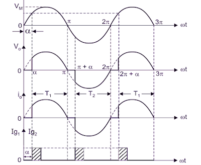
Soft starters are an electronic actuator based on power electronics switch (SCR) whoe makes an electrical controller which increase voltage gradually by cutting the wave form of the power supply using a variable firing angle ,which varies from the starting voltage to the nominal operating voltage in a period of time generally( e.g from 0 rpm to 1500 rpm in 3sec) which helps the motor to achieve a smooth acceleration.These devices offer precise control, minimizing inrush current and mechanical stress.
but on the other hand due to the switching process of SCR who cut the voltage and the current wave forms , so they increase the THD (Total Harmonic Distortion) by introducing harmonics in the power supply but just for a few seconds for this reason the soft starter represents a very suitable choice in induction motor starting process.
Variable Freguency Drive (VFD):
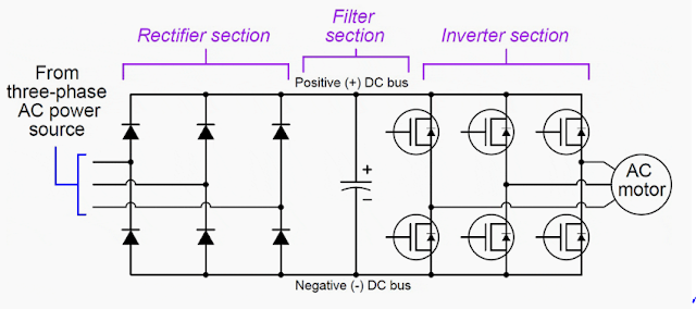
VFDs are the beast of electrical drives it offers the most sophisticated and flexible motor control.due to the strong architecutre which contain in the first level rectifier and filtring circuit and in the second block it come the inverter which provides a variable frequency and voltage to achieve precise speed control .switches of VFD generally are MOSFET or IGBT it depends on the maximum frequency and voltage required for the motor and application these switches are controlled by PWM controller , so VFD eliminating inrush current and minimizing mechanical stress offering a great speed and torque variation for induction motors in various applications .
Torque-Speed Curves
Torque-Speed Curve:
The torque-speed curve illustrates the relationship between motor torque and its operating speed. The shape of this curve varies depending on the motor type and load. During startup, the motor operates at a low speed and produces high torque. As it accelerates, the torque decreases until it reaches a point of equilibrium where the load torque matches the motor's output torque. Beyond this point, the motor operates at a constant speed, and the torque decreases linearly with increasing speed.
In conclusion, understanding the starting methods of three-phase induction motors is crucial for safe and efficient motor operation. By selecting the appropriate starting method and controlling inrush current, you can ensure the longevity of the motor, reduce energy consumption, and improve the overall performance of the connected machinery. Additionally, being aware of torque-speed curves helps in designing systems that can handle variable loads and operate smoothly under changing conditions.


